Output Devices
In the previous chapters, the microcontroller was mainly used to receive information from the physical world. A push button produced a digital input signal, while the potentiometer and the LDR produced analog input signals. These signals were read by the microcontroller and converted into values that could be processed by the program.
Output devices operate in the opposite direction. Instead of receiving information from the physical world, the microcontroller produces an electrical signal that causes an observable physical effect. Depending on the connected device, this effect may be light, sound, movement, heat, or the activation of another electrical circuit.
This chapter introduces two fundamental methods for controlling output devices. First, a GPIO pin (General Purpose Input/Output) is used as a digital output to switch an LED completely on or completely off. After that, Pulse Width Modulation, commonly abbreviated as PWM, is introduced as a method for controlling the apparent brightness of the LED.
An LED is used throughout the chapter because its response is immediately visible and because it can be controlled directly from a GPIO when it is connected using a suitable current-limiting resistor.
Digital Output
As explained in the chapter on Sensors and Signals, a digital signal represents a limited number of discrete states. For the GPIO pins used in this chapter, those states are represented using the logic values LOW and HIGH.
When a GPIO pin is configured as an output, the microcontroller actively drives the pin toward one of these two states. A LOW output corresponds approximately to 0 V, while a HIGH output corresponds approximately to the logic supply voltage of the microcontroller, which is 3.3 V for the ESP32.
It is important to distinguish between the logic state produced by the GPIO and the physical effect caused by the connected circuit. The words HIGH and LOW describe electrical logic states. They do not inherently mean that a device is on or off.
For example, an LED connected between a GPIO and ground will normally illuminate when the GPIO is set to HIGH. However, a circuit can also be designed so that the device activates when the GPIO is set to LOW. The result depends on how the device is electrically connected.
Before a GPIO can be controlled, it must be configured as an output using pinMode():
pinMode(pin, OUTPUT);
The state of a digital output is controlled using the Arduino function digitalWrite():
digitalWrite(pin, state);
The first argument identifies the GPIO pin, while the second argument specifies either HIGH or LOW. This configuration tells the microcontroller that the program intends to produce an electrical signal on the pin rather than read a signal from it.
The Built-In LED
The first output example uses the built-in LED on the development board, see the chapter Microcontroller to identify the location of the built-in LED in the development-board in the AMC Core Kit.
Using the built-in LED avoids the need to construct an external circuit and makes it possible to concentrate on the program and the upload process.
The built-in LED is a component of the development board. It is not a component contained directly inside the ESP32 microcontroller. This distinction follows the terminology introduced in the chapter on Disambiguations: the ESP32 is the microcontroller or system-on-chip, while the complete development board contains additional components such as voltage regulation, USB communication hardware, connectors, and, depending on the board, one or more LEDs.
The Arduino framework provides the identifier LED_BUILTIN to refer to the GPIO connected to the built-in LED:
LED_BUILTIN
Using this identifier is preferable to immediately writing a GPIO number directly into the program. The GPIO used for the built-in LED can vary between development boards, while LED_BUILTIN expresses the purpose of the pin without requiring the program to depend directly on a specific number.
Not every ESP32 development board includes a controllable built-in LED. In addition, some boards may use the logic states in the opposite way because of how the LED circuit is connected. The board documentation and pinout should therefore be checked when the observed behavior differs from the expected result.
Turning the Built-In LED On
The following program configures the built-in LED pin as an output and then sets it to HIGH:
#include <Arduino.h>

void setup() {
    pinMode(LED_BUILTIN, OUTPUT);
    digitalWrite(LED_BUILTIN, HIGH);
}

void loop() {

}
The instruction
pinMode(LED_BUILTIN, OUTPUT);
configures the GPIO connected to the LED as an output. The next instruction
digitalWrite(LED_BUILTIN, HIGH);
sets the output to the logic-high state.
Both instructions are placed inside setup() because the configuration and the initial output state only need to be established once when the microcontroller starts or is reset.
The loop() function remains empty. This does not prevent the LED from remaining illuminated. A GPIO output retains its most recently assigned state until the program changes it, the microcontroller is reset, or power is removed.
After compiling and uploading the program, the built-in LED should remain on. If the LED remains off, the development board may use an active-low LED circuit. In that case, LOW may illuminate the LED and HIGH may switch it off.
Turning the Built-In LED Off
To change the output state, the value passed to digitalWrite() is changed from HIGH to LOW:
#include <Arduino.h>

void setup() {
    pinMode(LED_BUILTIN, OUTPUT);
    digitalWrite(LED_BUILTIN, LOW);
}

void loop() {

}
The configuration of the GPIO has not changed. It is still configured as an output. Only the logic state produced by the pin has been modified.
This simple change demonstrates the basic principle of digital output control. The program selects one of two logic states, and the connected circuit converts that electrical state into a physical result.
Changing the Output Repeatedly
Placing digitalWrite() inside setup() produces a fixed output state. To change the state continuously while the program is running, the instructions can instead be placed inside loop().
The following program alternates between HIGH and LOW:
#include <Arduino.h>

void setup() {
    pinMode(LED_BUILTIN, OUTPUT);
}

void loop() {
    digitalWrite(LED_BUILTIN, HIGH);
    delay(1000);

    digitalWrite(LED_BUILTIN, LOW);
    delay(1000);
}
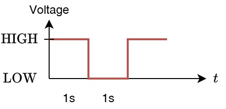
The LED is first switched to one state and held there for 1000 milliseconds. It is then switched to the opposite state and held there for another 1000 milliseconds. When the end of loop() is reached, the sequence begins again.
The resulting signal can be represented as:
 |
|---|
| Signal levels. |
Although the LED alternates between being illuminated and not illuminated, the electrical signal is still digital. At every instant, the GPIO is either HIGH or LOW. There are no intermediate output states in this example.
Controlling an External LED
The built-in LED is useful as a first example, but it hides most of the electrical circuit. The LED, its resistor, and the connection to the GPIO already exist on the development board.
To understand how a program controls a physical output circuit, the same principle can be reproduced using an external LED connected to a GPIO header pin.
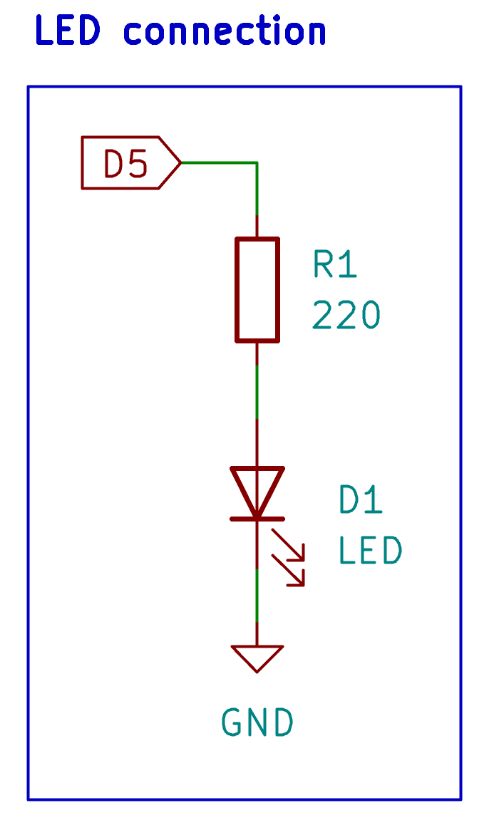
In this example, the LED is connected to GPIO 5. The circuit also contains a 220 Ω resistor, which limits the current flowing through the LED.
The circuit can be represented schematically as:
 |
|---|
| LED Schematic. |
The LED is a polarized component. Its orientation therefore matters. The anode must be connected toward the GPIO output, while the cathode must be connected toward ground.
For a conventional through-hole LED, the cathode is commonly identified by the shorter lead and by the flat side of the plastic package. These indicators are useful during breadboard construction, although the component datasheet should be consulted when the orientation is uncertain.
The resistor and LED are connected in series. Because the same current flows through all components in a series circuit, the resistor may be placed before or after the LED without changing its current-limiting function.
The resistor is necessary because an LED does not limit its own current sufficiently. Connecting an LED directly between a GPIO pin and ground may allow excessive current to flow, potentially damaging the LED or the microcontroller output.
The circuit should be assembled while the development board is disconnected from USB power. Before reconnecting the board, verify the LED orientation, resistor value, breadboard connections, GPIO connection, and ground connection. The breadboard connection principles described in Breadboard and Schematic apply in the same way as in the previous circuit examples.
Representing the External Connection in the Program
The physical connection must be represented correctly in the program. GPIO 5 can be assigned to a named constant:
const int LED_PIN = 5;
The name LED_PIN describes the purpose of the connection, while the value 5 identifies the GPIO used by the circuit.
This distinction is important. LED_PIN is a name created by the programmer. GPIO 5 is a hardware resource of the microcontroller. The development-board header provides the physical connection through which that GPIO can be accessed.
Using a named constant makes the program easier to read and modify. If the LED is later connected to another suitable GPIO, only the constant needs to be changed.
Turning the External LED On
The external LED can be switched on using the same functions that were used for the built-in LED:
#include <Arduino.h>

const int LED_PIN = 5;

void setup() {
    pinMode(LED_PIN, OUTPUT);
    digitalWrite(LED_PIN, HIGH);
}

void loop() {

}
The instruction
pinMode(LED_PIN, OUTPUT);
configures GPIO 5 as an output. The instruction
digitalWrite(LED_PIN, HIGH);
then drives the GPIO toward 3.3 V.
With the LED connected from the GPIO toward ground, current flows through the resistor and the LED. The LED therefore illuminates.
Turning the External LED Off
The LED can be switched off by changing the output state to LOW:
#include <Arduino.h>

const int LED_PIN = 5;

void setup() {
    pinMode(LED_PIN, OUTPUT);
    digitalWrite(LED_PIN, LOW);
}

void loop() {

}
When the output is LOW, both ends of the LED circuit are approximately at ground potential. There is therefore no significant voltage difference across the LED and resistor, and no current flows through the circuit.
The same external LED can also be made to blink by moving the state changes into loop():
#include <Arduino.h>

const int LED_PIN = 5;

void setup() {
    pinMode(LED_PIN, OUTPUT);
}

void loop() {
    digitalWrite(LED_PIN, HIGH);
    delay(1000);

    digitalWrite(LED_PIN, LOW);
    delay(1000);
}
The program is almost identical to the built-in LED example. Only the identifier used to select the output pin has changed.
This illustrates an important property of GPIO-based programming: the same software operation can control different physical circuits as long as the program uses the correct GPIO and the connected circuit is electrically compatible.
Verifying the External LED Circuit
When the external LED does not behave as expected, the software and the physical circuit should be verified separately.
First, confirm that the program was compiled and uploaded to the correct board. Check that LED_PIN contains the same GPIO number as the physical connection and that the pin has been configured using OUTPUT.
After that, inspect the circuit. The LED may be reversed, the resistor may be inserted into an incorrect breadboard row, or the ground connection may be missing. It is also possible to connect the signal wire accidentally to a neighboring header pin.
If the LED remains illuminated independently of the program, it may have been connected to the 3.3 V supply pin instead of GPIO 5. In that case, the microcontroller cannot control the LED because the circuit is connected directly to the power supply.
Hardware and software errors can produce similar visible results. For this reason, changing the program repeatedly without verifying the physical circuit is not an effective troubleshooting method.
The Limitation of ON/OFF Control
A digital output is sufficient when the connected device only needs two states. An indicator LED may need to show whether a system is active. A relay may need to be energized or released. A digital control input may need to be enabled or disabled.
However, many output devices require more than simple ON/OFF control. It may be necessary to adjust the apparent brightness of an LED, the speed of a motor, the average power supplied to a heater, or the intensity of another actuator.
A standard digital GPIO cannot directly produce every voltage between 0 V and 3.3 V. It can only produce the two digital logic states.
This limitation can be addressed by changing how long the output remains in each state.
Instead of keeping the GPIO continuously HIGH or continuously LOW, the microcontroller can switch rapidly between both states. By controlling the proportion of time spent in the high state, the program can control the average energy delivered to the connected device.
This method is called Pulse Width Modulation.
Pulse Width Modulation
Pulse Width Modulation, abbreviated as PWM, is a method of controlling an output by repeatedly switching a digital signal between HIGH and LOW.
At every instant, the GPIO is still in one of the two digital states. PWM does not create additional logic levels and does not turn the GPIO into a true analog-voltage output.
A PWM signal is defined primarily by its frequency and its duty cycle.
The frequency describes how often the complete switching cycle repeats. It is measured in hertz, where one hertz corresponds to one cycle per second.
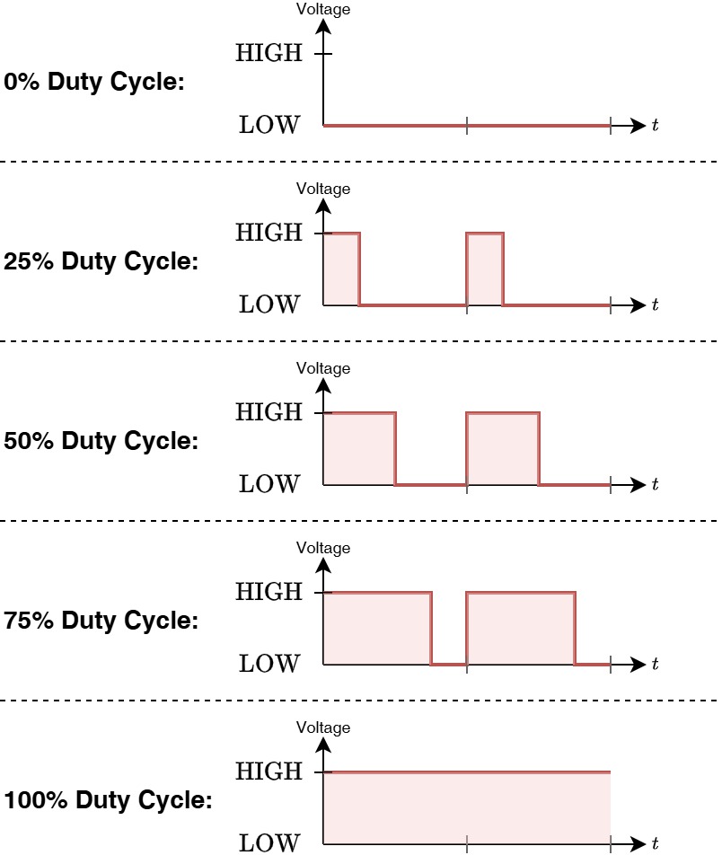
The duty cycle describes the proportion of each cycle for which the signal remains HIGH:
duty cycle = high time / complete period × 100%
A duty cycle of 0% means that the signal is never high. The output remains continuously LOW.
A duty cycle of 50% means that the signal is high for half of each cycle and low for the other half.
A duty cycle of 100% means that the signal remains continuously HIGH.
The difference can be represented as:
 |
|---|
| PWM duty cicles. |
When PWM is used to control an LED, the LED repeatedly switches on and off. If the switching frequency is sufficiently high, the individual transitions are not normally visible. Instead, the eye perceives an approximately steady brightness.
A low duty cycle keeps the LED on for only a small part of each cycle, producing a low apparent brightness. A higher duty cycle keeps it on for a larger part of the cycle, producing a higher apparent brightness.
Producing PWM with analogWrite()
The Arduino framework provides the function analogWrite() as a simple interface for generating PWM:
analogWrite(pin, value);
Despite its name, analogWrite() does not produce a continuously variable analog voltage on an ESP32 GPIO. The pin still switches between LOW and HIGH. The numerical value controls the duty cycle of this switching signal.
For the default 8-bit range, the value can vary from 0 to 255.
A value of 0 corresponds to a 0% duty cycle, while a value of 255 corresponds approximately to a 100% duty cycle. A value near the middle of the range produces a duty cycle of approximately 50%.
| PWM value | Approximate duty cycle | Expected LED behavior |
|---|---|---|
0 | 0% | Off |
64 | 25% | Low apparent brightness |
128 | 50% | Medium apparent brightness |
192 | 75% | High apparent brightness |
255 | 100% | Fully on |
The following program applies several fixed PWM values to the external LED:
#include <Arduino.h>

const int LED_PIN = 5;

void setup() {
    pinMode(LED_PIN, OUTPUT);
}

void loop() {
    analogWrite(LED_PIN, 0);
    delay(1000);

    analogWrite(LED_PIN, 64);
    delay(1000);

    analogWrite(LED_PIN, 128);
    delay(1000);

    analogWrite(LED_PIN, 192);
    delay(1000);

    analogWrite(LED_PIN, 255);
    delay(1000);
}
Each value is maintained for one second before the program advances to the next value.
This makes it possible to observe the relationship between the numerical PWM value and the resulting LED brightness. The brightness may not appear to change in perfectly equal visual steps, even though the numerical values change by equal amounts. Human brightness perception is not linear.
Internally, the ESP32 uses a hardware peripheral to generate the repeated switching signal. The Arduino framework handles the required peripheral configuration when analogWrite() is used. Direct configuration of the PWM frequency, channel, and resolution is therefore not required for this introductory example.
Fading the External LED
A gradual fade can be produced by changing the PWM value in small steps.
To fade the LED in, the program starts with a value of 0 and repeatedly increases it until it reaches 255:
for (int brightness = 0; brightness <= 255; brightness++) {
    analogWrite(LED_PIN, brightness);
    delay(10);
}
The variable brightness begins at 0. During each iteration of the loop, its current value is passed to analogWrite(). The variable is then increased by one.
The delay does not define the PWM frequency. The PWM signal itself is produced by the microcontroller hardware. The delay only determines how long the program waits before selecting the next duty-cycle value.
Without this delay, all values would be processed so quickly that the transition would be difficult to observe.
The fade-out process uses the opposite sequence. It begins at 255 and decreases the PWM value until it reaches 0:
for (int brightness = 255; brightness >= 0; brightness--) {
    analogWrite(LED_PIN, brightness);
    delay(10);
}
Combining both sequences produces a continuous fade-in and fade-out effect:
#include <Arduino.h>

const int LED_PIN = 5;

void setup() {
    pinMode(LED_PIN, OUTPUT);
}

void loop() {
    // Fade in by gradually increasing the PWM duty cycle.
    for (int brightness = 0; brightness <= 255; brightness++) {
        analogWrite(LED_PIN, brightness);
        delay(10);
    }

    // Fade out by gradually decreasing the PWM duty cycle.
    for (int brightness = 255; brightness >= 0; brightness--) {
        analogWrite(LED_PIN, brightness);
        delay(10);
    }
}
The program repeatedly follows the same sequence:
The variable named brightness does not directly represent physical light intensity. It represents the numerical value passed to the PWM output function. That value determines the duty cycle, which influences the average current through the LED and therefore its apparent brightness.
This distinction is useful when interpreting program variables. A variable name describes the intended meaning within the program, but the actual physical effect depends on the complete chain between software, electrical signal, circuit, and output device.
Digital Output and PWM
Digital ON/OFF control and PWM both use the same two electrical logic states. The difference lies in how the states are used over time.
With normal digital output control, the GPIO remains in its assigned state until the program changes it. With PWM, the GPIO repeatedly switches between HIGH and LOW, while the duty cycle determines the proportion of time spent in the high state.
| Property | Digital ON/OFF control | PWM control |
|---|---|---|
| Instantaneous GPIO states | LOW or HIGH | LOW or HIGH |
| Main control value | Logic state | Duty cycle |
| Switching behavior | Changes when instructed by the program | Repeats automatically |
| LED result | Off or fully on | Adjustable apparent brightness |
| Arduino function | digitalWrite() | analogWrite() |
PWM should therefore not be understood as an additional voltage state. It is a timing-based method that controls a physical device using the same digital output levels.
GPIO Outputs and Power
The external LED circuit can be controlled directly from the GPIO because the required current is small and is limited using the resistor.
This does not mean that a GPIO can directly power every output device.
Devices such as motors, pumps, solenoids, relays, heating elements, high-power LEDs, and large buzzers may require substantially more current or voltage than a GPIO can safely provide. Connecting these devices directly to the microcontroller may damage the GPIO, the development board, or the connected device.
For these loads, the GPIO is normally used only as a control signal. A transistor, MOSFET, relay driver, motor driver, or another suitable interface circuit controls the larger current supplied by an external power source.
Inductive devices, including motors, solenoids, and mechanical relays, may also require protection components to suppress the voltage generated when their current is interrupted.
The GPIO determines what the output device should do, while the driver circuit and external power supply provide the required electrical energy.
Summary
An output device allows a microcontroller program to produce a physical effect.
A GPIO configured as a digital output can produce the logic states LOW and HIGH. The pin is configured using pinMode() and its state is controlled using digitalWrite().
The built-in LED provides a simple first output because it does not require an external circuit. An external LED extends the same principle to a physical GPIO header, breadboard, current-limiting resistor, and polarized component.
Digital output control is suitable when a device only needs to be switched on or off. When intermediate control is required, Pulse Width Modulation can be used.
PWM repeatedly switches a digital GPIO between LOW and HIGH. The duty cycle determines the proportion of time for which the signal remains high. For an LED, this controls the average current and therefore its apparent brightness.
The Arduino function analogWrite() provides a simple PWM interface. A gradually changing PWM value can be used to produce a fade-in and fade-out effect.
Finally, a GPIO should be understood primarily as a control-signal source. Small loads such as an indicator LED can be controlled directly when the circuit is designed correctly, while higher-power output devices require suitable driver circuits and external power.