Introduction to Programming Microcontrollers
This chapter introduces the basic workflow required to program a microcontroller. The focus is not only on installing software, but also on understanding the purpose of each step: writing source code, compiling it, uploading it to the board, and observing the result on the physical hardware.
The examples in this chapter use VS Code, PlatformIO, and the Arduino framework. The microcontroller board used in the AMC Core Kit is the DOIT ESP32 DevKit, which is based on the ESP32 microcontroller.
Ways to Program Microcontrollers
There are several ways to program a microcontroller. The correct approach depends on the board, the manufacturer, the level of hardware control required, and the development environment selected for the project. In general, these approaches can be separated into two broad categories: vendor-specific development and vendor-agnostic frameworks.
Vendor-specific development uses tools and libraries provided by the manufacturer of the microcontroller. For example, Espressif provides the official development framework for ESP32 microcontrollers, commonly known as ESP-IDF (Espressif IoT Development Framework). This framework gives direct access to ESP32-specific features such as Wi-Fi, Bluetooth, timers, FreeRTOS tasks, memory configuration, and low-level peripheral control. It is powerful, but it also expects the programmer to understand more about the internal structure of the microcontroller, in this case the ESP32 microcontroller.
Other manufacturers provide similar toolchains for their own devices. Microchip, formerly Atmel, provides tools for AVR and other microcontrollers. These are commonly associated with boards based on chips such as the ATmega328P, which is in fact the microcontroller in the quite popular Arduino UNO board. STMicroelectronics provides development tools for STM32 microcontrollers, including STM32CubeIDE, STM32CubeMX and STM32CubeProgrammer. These tools are widely used in professional embedded systems, industrial control, robotics, and motor-control applications.
The advantage of vendor-specific development is control. You as the programmer can configure the device in detail and use features that may not be available through vendor-agnostic frameworks. The disadvantage is that this approach is usually less beginner-friendly. It may require knowledge of hardware registers, clock configuration, memory layout, interrupts, device drivers, and manufacturer-specific documentation.
A second approach is to use a vendor-agnostic framework. These frameworks provide a more general programming interface that can be used across different boards and microcontroller families. The most common example is the Arduino framework. Although people often refer to it as the “Arduino language,” it is more accurate to understand it as a simplified C++ programming environment with a large ecosystem of libraries and examples. See Disambiguations.
The Arduino framework provides functions such as pinMode(), digitalWrite(), analogRead(), delay(), and Serial.print(). These functions hide many of the low-level details and make it easier to start writing programs that interact with hardware. This does not mean that Arduino is only for simple projects; it means that it provides a practical starting point. Many concepts learned through Arduino-based development are still relevant when moving later to lower-level embedded programming.
Another vendor-agnostic option is MicroPython, which allows some microcontrollers to be programmed using a Python-like language. MicroPython is useful for quick experimentation and educational work, especially when the goal is to test ideas rapidly. However, for AMC the main workflow uses the Arduino framework through PlatformIO, because it provides a good balance between accessibility, structure, performance, and compatibility with the ESP32 board used in the kit.
Development Environment Used in AMC
Before a microcontroller can be programmed, the correct development environment must be installed. A development environment is the collection of tools used to write, compile, upload, and debug code.
In this chapter, the editor is Visual Studio Code, usually called VS Code. VS Code is not itself a microcontroller development environment, but it becomes one when extended with the correct tools. The tool used for this purpose is PlatformIO.
PlatformIO is an embedded development environment that runs inside VS Code. It manages board definitions, frameworks, compilers, upload tools, libraries, and project configuration. Instead of manually installing several separate tools for the ESP32, PlatformIO downloads and organizes the required components automatically.
This is especially useful in a teaching environment because it gives all students a consistent workflow. Once PlatformIO is installed, the same basic process can be used for many different boards and microcontroller families.
Setting Up VS Code and PlatformIO
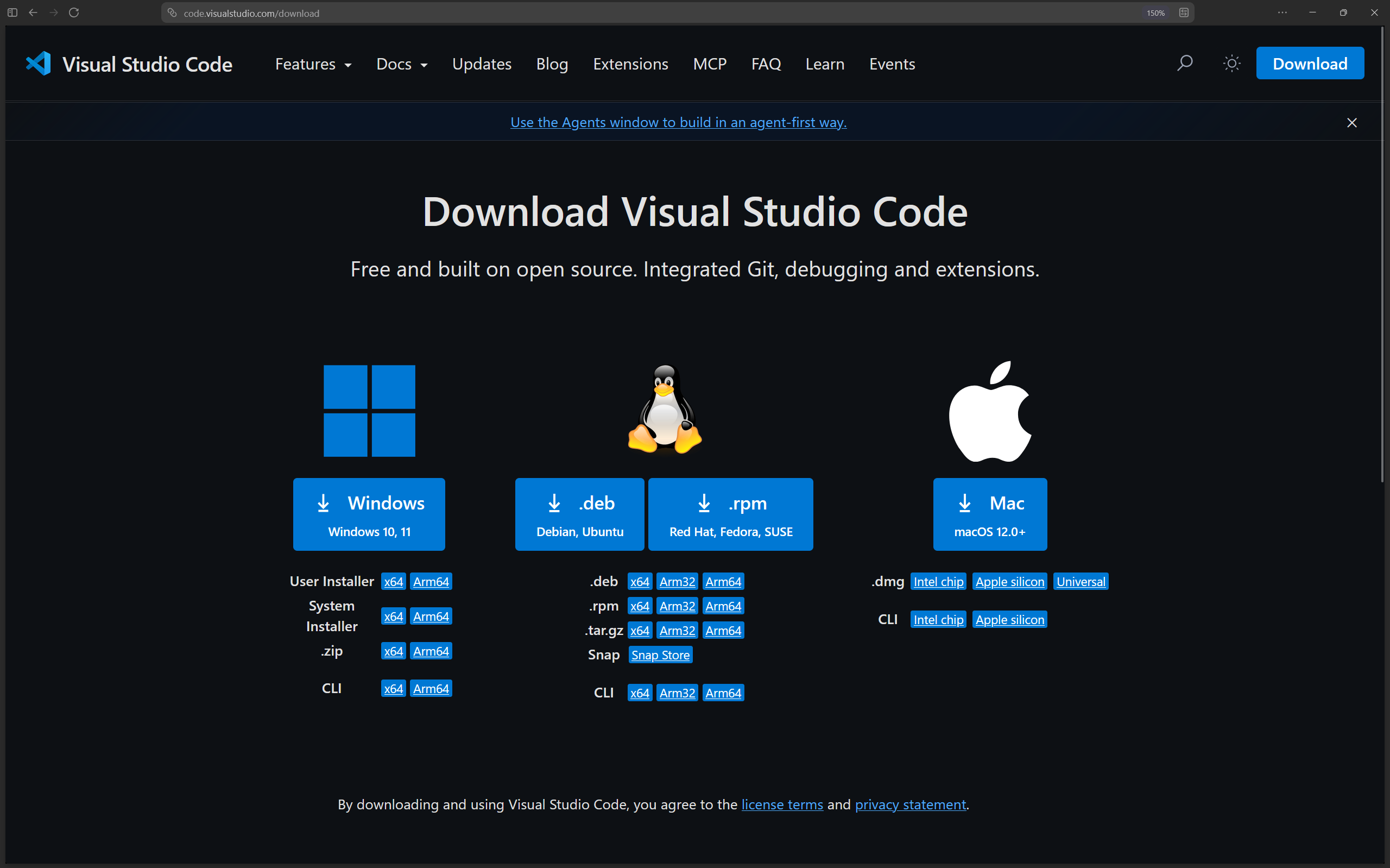
The first part of the setup is to install VS Code. Go to the official VS Code download page and select the installer for your operating system.
 |
|---|
| VS Code download page. |
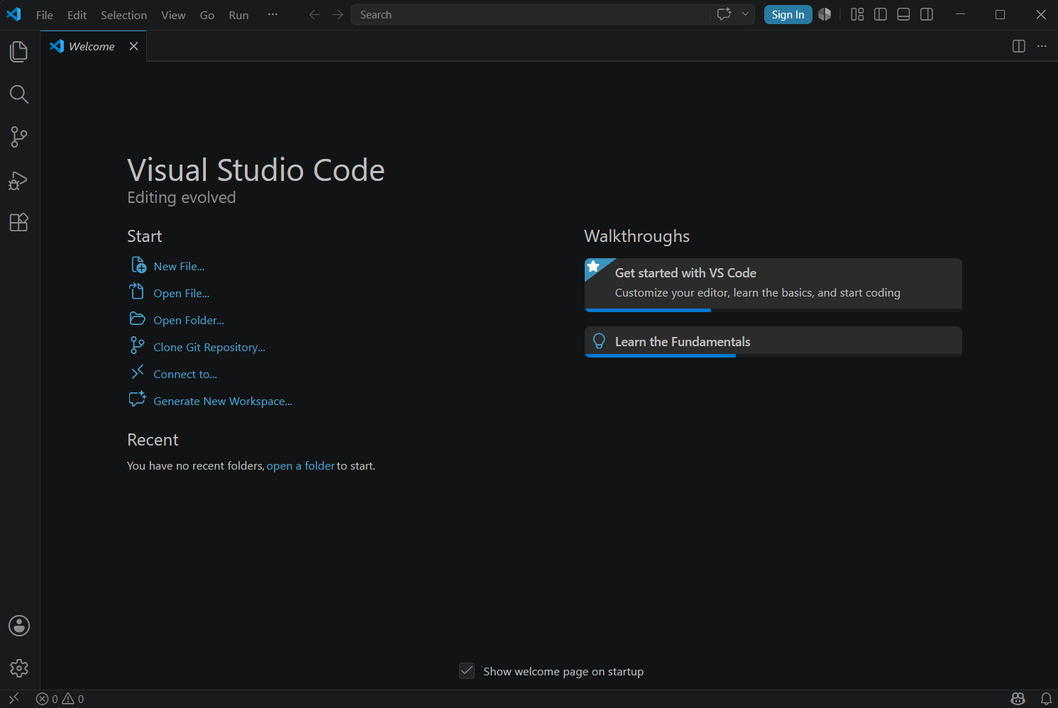
After downloading the installer, run it and follow the installation wizard. The default options are usually sufficient. Once the installation is complete, open VS Code. At this point, VS Code is only a general-purpose editor. The microcontroller development tools will be added in the next steps.
 |
|---|
| VS Code installed and opened. |
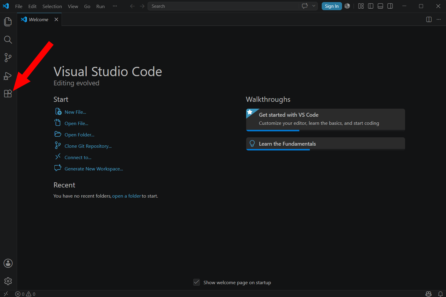
Inside VS Code, open the Extensions panel from the left-side toolbar. Extensions are add-ons that provide extra functionality. In this case, the required extension is PlatformIO IDE.
 |
|---|
| VS Code extensions panel. |
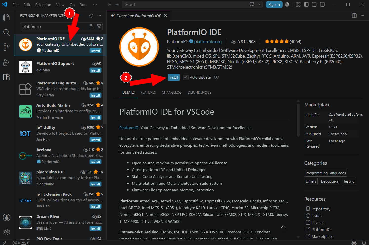
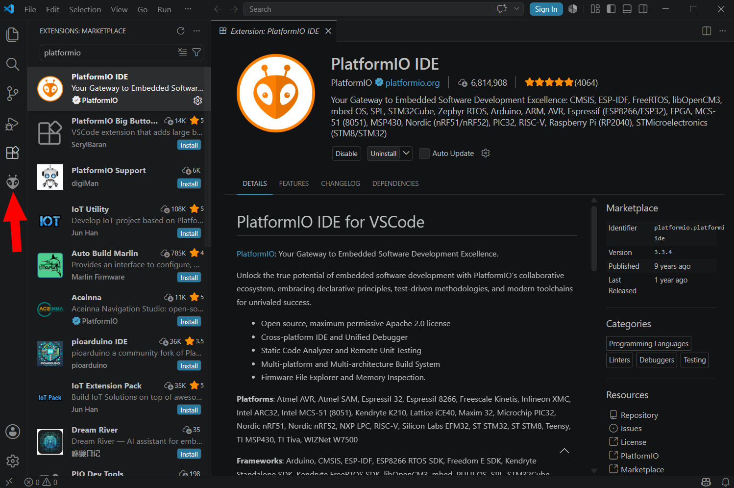
Search for PlatformIO and install the PlatformIO IDE extension. This extension adds the PlatformIO interface to VS Code and provides the tools needed to create, compile, and upload embedded projects.
 |
|---|
| Search for and install the PlatformIO IDE extension. |
After the extension is installed, a PlatformIO icon appears in the left-side panel. Open it. The first time PlatformIO starts, it may take a few minutes to initialize. During this process, PlatformIO prepares its internal environment and may download additional tools required for embedded development.
 |
|---|
| Open PlatformIO for the first time. |
When PlatformIO finishes loading, the development environment is ready. The next step is to create a project for the ESP32 board.
Creating the First PlatformIO Project
A PlatformIO project contains all the files required to build and upload a program for a specific microcontroller board. This includes the source code, configuration file, libraries, and build folders generated by PlatformIO.
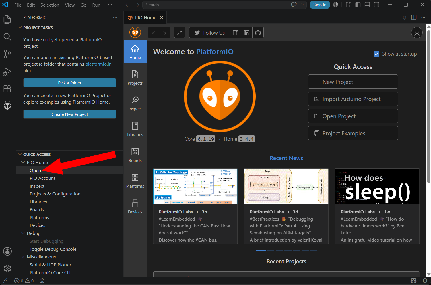
Open PlatformIO Home and click Open to access the main PlatformIO menu.
 |
|---|
| Open the PlatformIO main menu. |
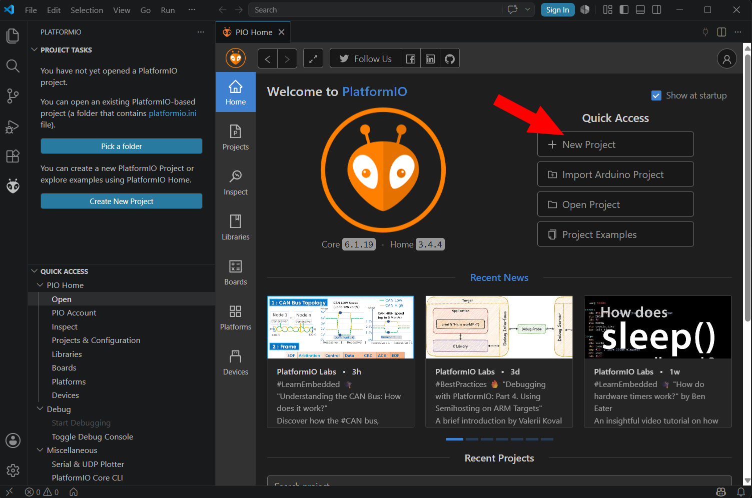
From the PlatformIO Home screen, create a new project. PlatformIO will open a project wizard where the basic project information must be entered.
 |
|---|
| Create a new PlatformIO project. |
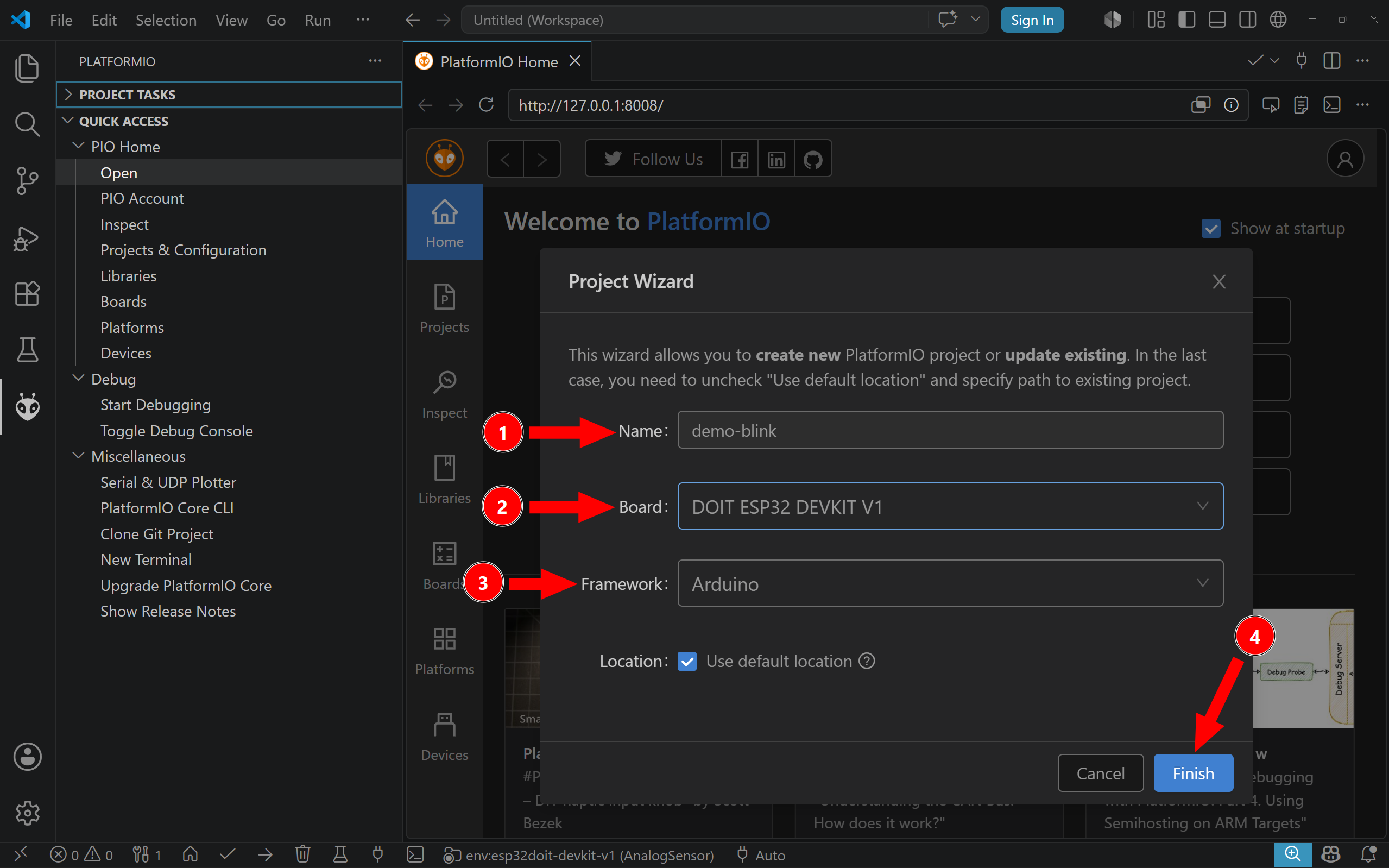
The project name can be any clear name that identifies the purpose of the project. In this example, the project is called demo-blink. Short and descriptive names are recommended, because microcontroller projects tend to multiply quickly during experimentation.
The board selection is more important. It tells PlatformIO which physical board will receive the program. For the AMC Core Kit, select DOIT ESP32 DEVKIT V1. This option corresponds to the ESP32 development board used in the kit. Some boards are electrically or mechanically similar to boards from other vendors, but the selected board must still match the actual target as closely as possible, because PlatformIO uses this setting to choose the correct upload method, memory layout, and build configuration.
The framework determines the programming environment used by the project. In this chapter, select Arduino. For the ESP32, another possible option is the vendor-specific Espressif framework, ESP-IDF. ESP-IDF is useful for more advanced ESP32 development, but the Arduino framework is the expected starting point for AMC exercises.
 |
|---|
| PlatformIO project setup. |
After entering the project information, click Finish. The first time a project is created for a particular board, PlatformIO may take several minutes to download the required platform packages, compiler, board files, and framework files. This is normal. Later projects using the same platform usually open faster because the required tools are already installed.
Understanding the PlatformIO Project Structure
Once the project has been created, VS Code shows the project folder in the file explorer. A minimal PlatformIO project contains several folders, but only a few of them are important at the beginning.
include/          Header files for the project
lib/              Project-specific external libraries
src/              Source code of the project
test/             Test files, when unit testing is used
platformio.ini    Project configuration file
The src folder contains the source code that will be compiled and uploaded to the board. For a basic Arduino-style project, the main file is usually called main.cpp. This is where the program is written.
The platformio.ini file is the project-level configuration file. It tells PlatformIO which board, platform, and framework are being used. A typical configuration for the DOIT ESP32 DevKit using the Arduino framework looks like this:
[env:esp32doit-devkit-v1]
platform = espressif32
board = esp32doit-devkit-v1
framework = arduino
The line platform = espressif32 tells PlatformIO that the project targets an Espressif ESP32 platform. The line board = esp32doit-devkit-v1 identifies the specific development board. The line framework = arduino tells PlatformIO to compile the project using the Arduino framework.
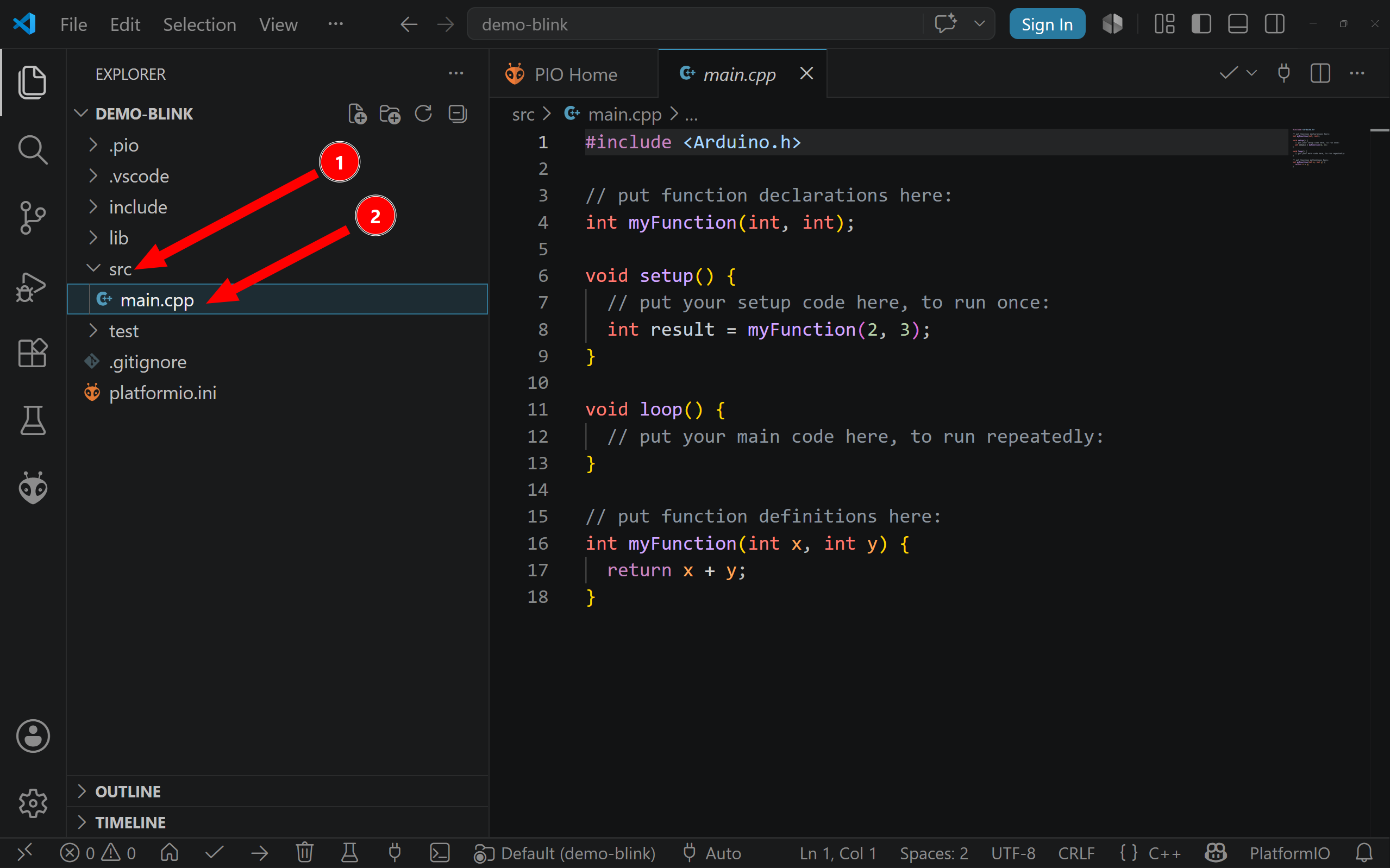
To open the main source file, expand the src folder and click main.cpp.
 |
|---|
Open main.cpp inside the src folder. |
Depending on the PlatformIO template version, the default main.cpp file may include example code or a sample function. For example, it may contain a function named myFunction(). This function is only included to demonstrate that additional functions can be defined in the program. It is not required for the microcontroller to work, and it can be removed when writing your own code.
The Basic Programming Workflow
Programming a microcontroller follows a repeated cycle. First, the source code is written in the editor. Then the code is compiled. If compilation succeeds, the compiled program is uploaded to the microcontroller. After upload, the board runs the program, and the result is tested on the physical hardware.
This cycle is repeated many times during development. Embedded programming is rarely written perfectly in one attempt. A typical workflow is to make a small change, compile the program, upload it, test the behavior, and then continue. This makes problems easier to locate because each change is small and controlled.
The word compile has a specific meaning. The code written by the programmer is human-readable C++ source code. The microcontroller cannot execute that text directly. During compilation, the compiler translates the source code into machine instructions for the target device. PlatformIO also links the program with the necessary Arduino and ESP32 framework code, producing a firmware file that can be stored in the microcontroller memory.
The words program, flash, and upload are often used to describe the same process. They mean transferring the compiled firmware from the computer into the memory of the microcontroller. Once this transfer is complete, the microcontroller resets and starts executing the new program.
Minimal Arduino-Style Program
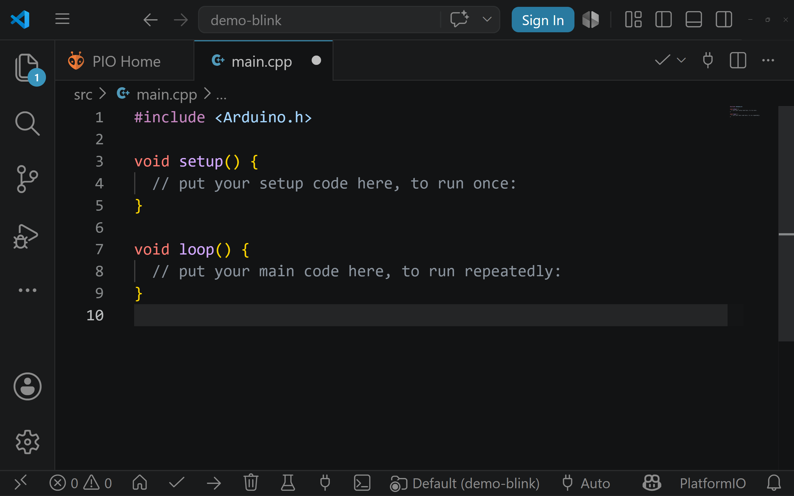
The smallest useful Arduino-style program has two required functions: setup() and loop().
 |
|---|
| Minimal Arduino-style program structure. |
The same program can be written as:
#include <Arduino.h>

void setup() {

}

void loop() {

}
The first line includes the Arduino framework:
#include <Arduino.h>
This line gives the program access to Arduino functions such as pinMode(), digitalWrite(), analogRead(), delay(), and Serial.begin(). In the Arduino IDE this include is often hidden, but in PlatformIO it is normally written explicitly.
The setup() function runs once when the microcontroller starts. It is used for initialization. For example, this is where pins are configured, serial communication is started, sensors are initialized, or initial output states are defined.
The loop() function runs after setup() has finished. Unlike setup(), it does not run only once. It repeats continuously while the microcontroller has power. This repeated execution is central to most embedded programs. A microcontroller usually waits for inputs, checks conditions, updates outputs, communicates with devices, and then repeats the same process again and again.
Although the minimal program above does not perform any visible action, it is still a valid program. It can be compiled and uploaded to the board. This is useful as a first test because it verifies that the toolchain, board selection, and upload connection are working before any circuit-specific code is introduced.
Compiling the Program
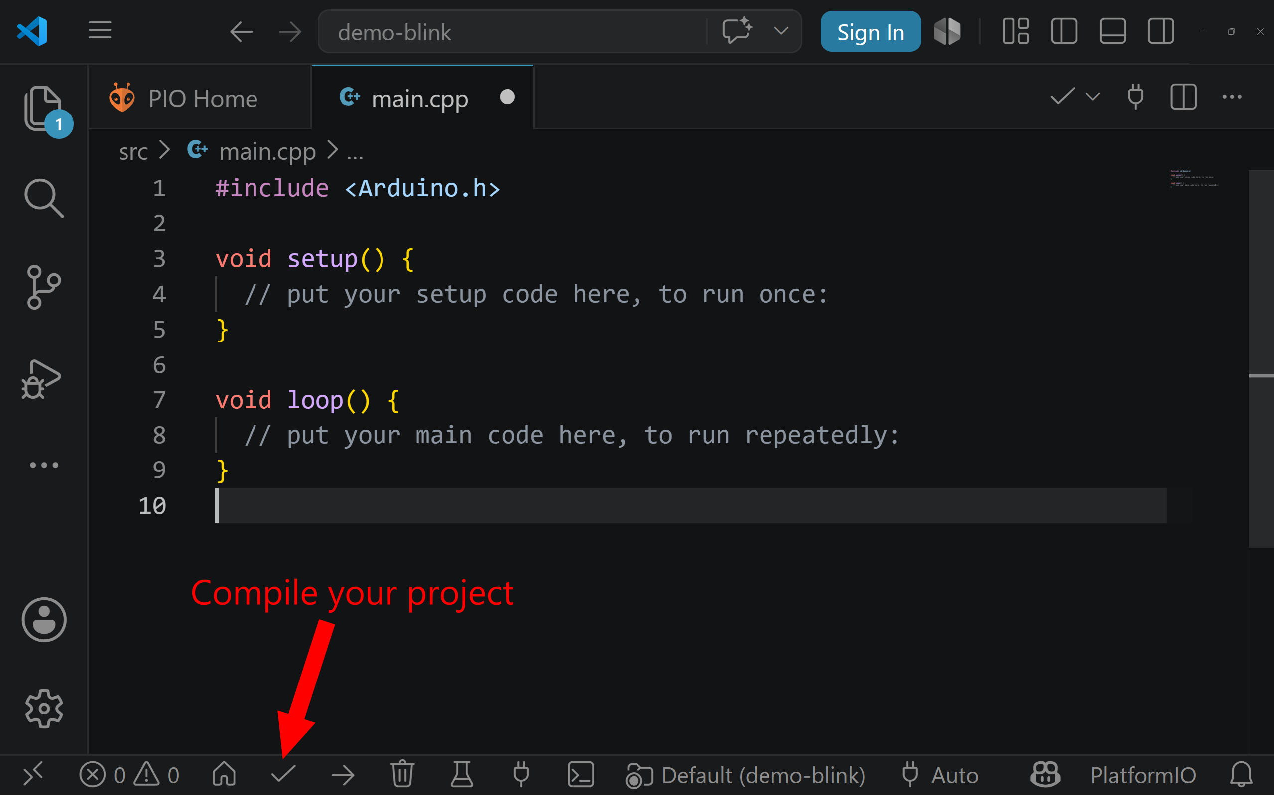
Before the program can be placed on the microcontroller, it must be compiled. In PlatformIO, compilation is usually started by clicking the Build button, represented by a check mark in the PlatformIO toolbar.
 |
|---|
| Compile code in platformio. |
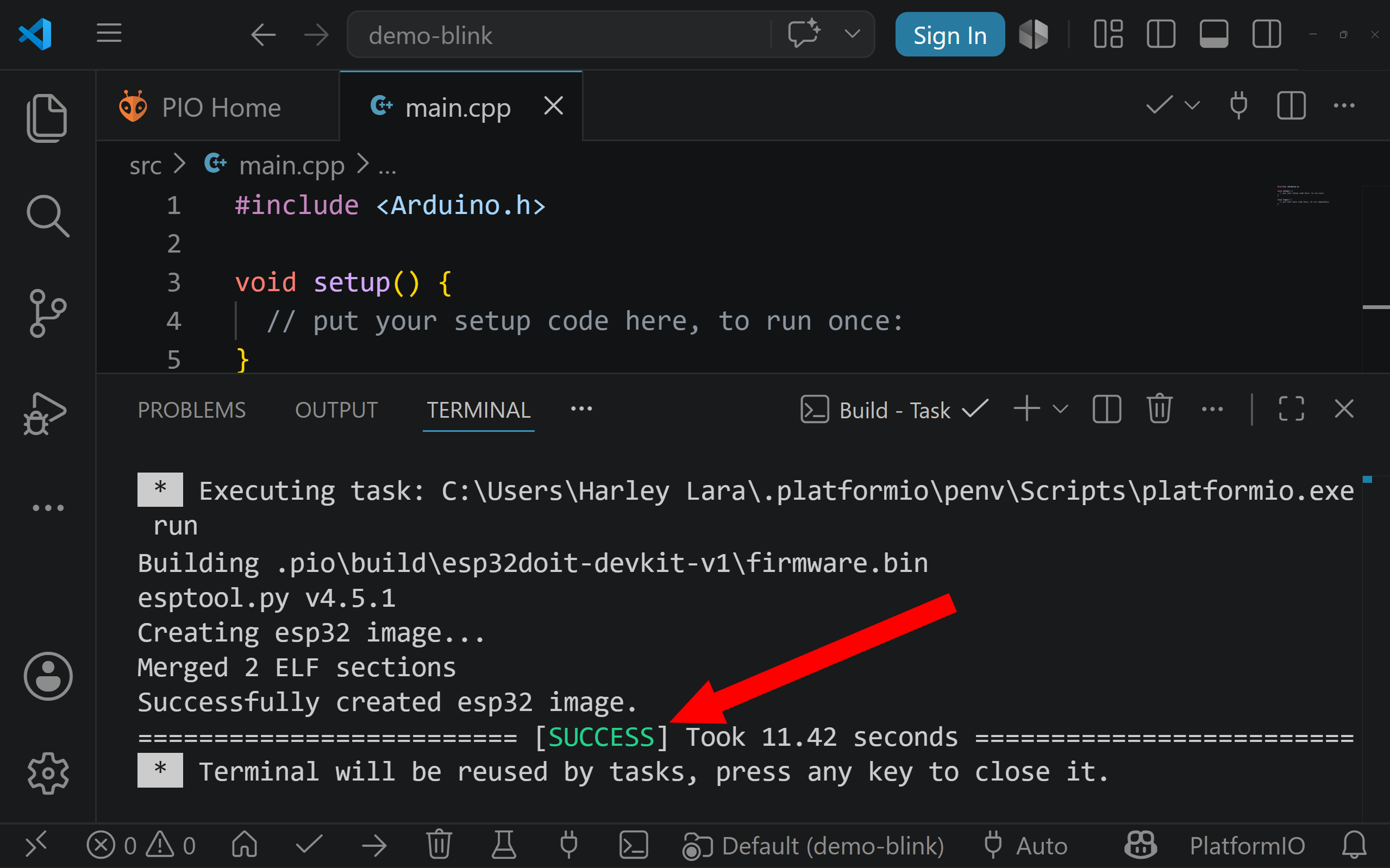
When the build process starts, PlatformIO reads the platformio.ini file and determines the selected board, platform, and framework. It then finds the source files in the src folder and passes them to the compiler. The compiler checks the syntax of the code, translates it into object files, and links it with the required framework libraries. If all steps succeed, PlatformIO creates a firmware file ready to be uploaded to the board.
 |
|---|
| Successfully compile code in platformio. |
If the program contains an error, the compilation fails. This does not damage the board. It simply means that PlatformIO could not produce valid firmware from the source code. The error message appears in the terminal panel at the bottom of VS Code. These messages can look difficult at first, but they usually contain useful information, including the file name, the line number, and the type of error.
A missing semicolon, for example, is a common beginner mistake:
digitalWrite(ledPin, HIGH)
The corrected version is:
digitalWrite(ledPin, HIGH);
A successful compilation means that the code is syntactically valid and can be converted into firmware for the selected board. It does not guarantee that the program logic is correct or that the circuit is wired properly. It only confirms that the program can be built.
Uploading the Program to the ESP32
After the program compiles successfully, the next step is to upload it to the ESP32 board. Connect the DOIT ESP32 DevKit to the computer using a USB cable. The cable must support data transfer. Some USB cables are designed only for charging and will not allow the computer to communicate with the board.
In PlatformIO, click the Upload button, usually represented by a right arrow. PlatformIO will compile the project if necessary, detect the serial port, place the ESP32 into programming mode, transfer the firmware, and reset the board so the new program starts running.
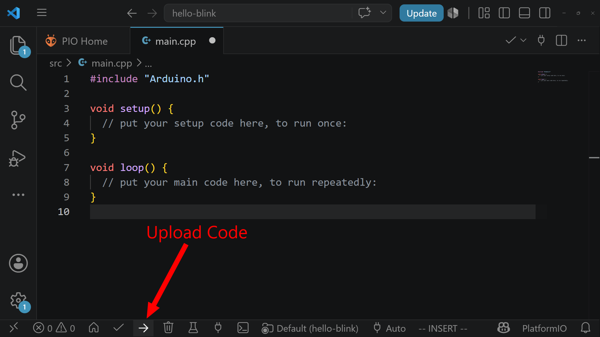 |
|---|
| Upload code in platformio. |
If the upload fails, the problem is usually related to the connection, board selection, serial port, or USB driver. Check that the board is connected correctly and that the selected board in platformio.ini matches the board being used. Also check that no other program, such as a serial monitor, is already using the same port.
On some ESP32 boards, the automatic reset circuit does not always place the board into programming mode reliably. If this happens, hold the BOOT button on the board while the upload begins, then release it once the upload starts. This manually forces the ESP32 into the correct mode for flashing.
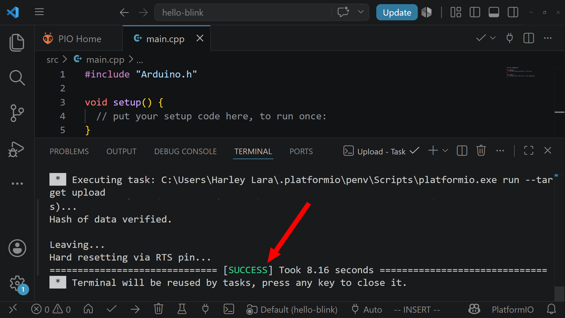 |
|---|
| Successful upload code in platformio. |
First Visible Program: Blink
A minimal empty program confirms that the board can be programmed, but it does not produce any visible behavior. The traditional first visible microcontroller program is called Blink. It turns an LED on and off repeatedly. In embedded systems, Blink plays the same role that “Hello, world!” plays in introductory software programming.
Many ESP32 development boards have an onboard LED connected to GPIO 2, although this can vary between board versions. The following program assumes that the onboard LED is connected to GPIO 2:
#include <Arduino.h>

const int ledPin = 2;

void setup() {
    pinMode(ledPin, OUTPUT);
}

void loop() {
    digitalWrite(ledPin, HIGH);
    delay(1000);

    digitalWrite(ledPin, LOW);
    delay(1000);
}
The variable ledPin stores the GPIO number used for the LED. Defining the pin as a named constant makes the program easier to read and easier to modify later. If the LED is connected to a different pin, only this value needs to be changed.
Inside setup(), the instruction pinMode(ledPin, OUTPUT); configures the pin as an output. A microcontroller pin can often be used in different modes, so the program must specify how the pin will be used.
Inside loop(), the instruction digitalWrite(ledPin, HIGH); sets the pin to a high voltage level. This usually turns the LED on. The instruction delay(1000); pauses the program for 1000 milliseconds, which is one second. Then digitalWrite(ledPin, LOW); sets the pin to a low voltage level, usually turning the LED off. A second delay keeps it off for one second before the loop repeats.
If the program uploads successfully but no LED blinks, the board may use a different onboard LED pin, or it may not have an onboard LED connected to a programmable GPIO. In that case, an external LED and resistor can be connected to a known GPIO pin on the breadboard.
Using the Serial Monitor
Not all programs produce visible output through an LED or other component. Sometimes the most useful output is text sent from the microcontroller back to the computer. This is done using serial communication.
The PlatformIO Serial Monitor allows the computer to receive and display messages sent by the ESP32 through the USB connection. This is one of the most useful debugging tools in beginner embedded programming.
A basic serial program looks like this:
#include <Arduino.h>

void setup() {
    Serial.begin(115200);
}

void loop() {
    Serial.println("Hello from the ESP32");
    delay(1000);
}
The instruction Serial.begin(115200); starts serial communication at a baud rate of 115200 bits per second. The Serial Monitor must be configured to use the same baud rate. If the baud rate in the monitor does not match the baud rate in the program, the text may appear corrupted or unreadable.
The instruction Serial.println("Hello from the ESP32"); sends a line of text from the ESP32 to the computer. Because this instruction is placed inside loop(), the message is printed repeatedly once per second.
Serial output is especially useful when working with sensors. A program can read a sensor value and print it to the Serial Monitor before that value is used to control another part of the circuit. This allows the programmer to check whether the sensor is working before adding more complex behavior.
Reading Programs as Hardware Behavior
When programming microcontrollers, the source code should not be read only as software. It should also be read as a description of hardware behavior. Each instruction may correspond to a physical action: a pin changing voltage, a sensor being read, a motor being activated, or data being sent to another device.
For example, the instruction:
digitalWrite(ledPin, HIGH);
is not only a line of code. It is a command that changes the electrical state of a physical pin on the microcontroller. If an LED circuit is connected to that pin correctly, the electrical change becomes visible as light.
This connection between code and circuit is what makes embedded programming different from ordinary desktop programming. A program can compile correctly and still fail because a wire is placed in the wrong row of the breadboard. Likewise, a circuit can be wired correctly and still fail because the program uses the wrong GPIO pin. Debugging therefore requires checking both the software and the hardware.
Common Problems During First Setup
The first setup of a microcontroller development environment can fail for several reasons. Compilation errors usually come from the source code. Upload errors usually come from the board connection, port configuration, or driver installation.
If compilation fails, read the terminal output carefully. Look for the first error message rather than the last one. A single syntax error can cause many additional messages, so the first reported problem is often the most useful one.
If upload fails, first check the USB cable. A charge-only cable is a common cause of failure because the board may receive power but cannot exchange data with the computer. Then check that the correct board is selected in platformio.ini. If the serial port is busy, close any open Serial Monitor or other application that may be using the board.
If the upload completes but the program does not behave as expected, check the GPIO number, the wiring, the polarity of components such as LEDs, and whether all parts of the circuit share a common ground. In microcontroller projects, software and hardware mistakes often look similar at first, so both must be inspected.
Good Development Practice
Microcontroller programs should be developed incrementally. Start with a minimal program that compiles and uploads successfully. Then add one feature at a time. For example, first blink an LED. Then read a button. Then use the button to control the LED. Then add serial output. Each step should be tested before continuing.
This approach reduces the number of possible causes when something goes wrong. If a program worked before one small change and failed afterward, the new change is probably related to the problem.
Clear names also matter. A program using names such as buttonPin, ledPin, and sensorValue is easier to understand than one using names such as x, y, and z. In embedded systems, readable names help connect the program to the physical circuit.
For example:
const int buttonPin = 4;
const int ledPin = 2;
is clearer than:
const int x = 4;
const int y = 2;
The first version shows the purpose of each pin directly. This becomes increasingly important as circuits become larger and programs become longer.
Summary
Programming a microcontroller involves more than writing code. The program must be written for the correct board, compiled with the correct framework, uploaded through the correct connection, and tested on real hardware. The development process combines software reasoning with circuit reasoning.
In AMC, the standard workflow uses VS Code, PlatformIO, the Arduino framework, and the DOIT ESP32 DevKit. VS Code provides the editor, PlatformIO manages the embedded development tools, the Arduino framework provides a practical programming interface, and the ESP32 board executes the uploaded program.
The foundation of an Arduino-style program is the pair of functions setup() and loop(). The setup() function runs once when the board starts, while the loop() function runs continuously afterward. This structure reflects the way many embedded systems operate: initialize the hardware, then repeatedly read inputs, process information, and update outputs.
Once this workflow is understood, the microcontroller becomes a programmable part of the circuit. It can read physical signals, make decisions in software, and control electronic components in response.